Meanwhile, I received my signals from Custom Signal Systems. He assembled the two BLMA Double Track Bridge kits, painted and installed the heads.
Testing of the signals was a breeze as all the micro wires were pre-tinned, color-coded, correct resistor installed, and ready to go. Also, the wires were safely routed down tubing to prevent any chafing of the micro insulation creating a short. I have been much more pleased with Custom Signal Systems than my experience with BeNScale signals.
I had researched various ways to control the signals. To do any sort of detection would be very expensive. With the size of my layout, it would simply be overkill. I just want to control the signals manually to add some realism to the operations. It was suggested to create a simple circuit board to control the signals. Custom Signal Systems offered to build me one (which I appreciate), but wanted a $100 the two boards required to control the signals at Utica. I wanted to save money, so I researched on how I could do it myself. I figured it couldn't be too hard. I found some videos on YouTube that helped with the basics. I felt I was ready and started creating a list of components required.
Btw, this guy has some great videos on the subject.
I found that the parts to be inexpensive and it would simply take a little time. Probably a little more than expected since I have never done any circuit board-type work previously, but still worth it as I would learn a new skill.
So, I went down to my local Radio Shack. Between there and Amazon, I was able to find the components I needed.
- 2 3/4" by 3 3/4" Perf Board
- Pack of 25 1A Rectifier Diodes (this will only allow current to flow only one way).
- 2 Pole 5mm Screw Terminal Blocks
- 22 Gauge solid core wire
Here is my control board for Utica using 6 stop rotary switches (only 4 stops will be used). It is printed out on paper and then applied to the back of 8x10 plexiglass (found at Home Depot). The rotary switches are installed on the plexiglass.

Here is a schematic of how it needs to function.

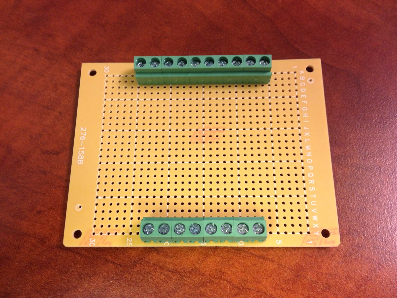
I installed the terminal blocks on the board. The bottom is the inputs from the rotary switches.
The top is the output to the signal head wire leads.

I added the diodes to the board.

Here is a view of the underside of the board.

Another view of the underside of the board showing the terminal posts.

Added the jumper wires between the diodes.

The final picture from the underside. I got a little sloppy with the red wire on the right. At the time though, we were dealing with some girl drama in the house, so I'm really not surprised. :-)
This evening, I soldered everything up and tested. I had one loose alligator clip (not anything wrong with the board) and then one loose connection that just needed a touch of solder. Otherwise, it works just as designed. I'm beyond ecstatic that I was able to pull this off. It isn't a complex board, but I made it. I'm proud!
This project made me feel all nerdy and I liked it! It was fun learning something new. Now, I wonder what else I can create on a perf board. I have already been looking into Arduino to find that I can control boards like this with an iPhone! Neat stuff! I would have to join forces with my friend Michael to get the programming straight, but between the two of us I'm confident we could pull it off.
Great job Steven !
ReplyDeleteI really like building my stuff on boards like this with those nice terminal strips that you used. I picked up an Arduino board about a year ago to experiment with. Got it doing a few things in simulations with the idea of using it to control staging yards. I think they would have lots of applications for our layouts.
Thanks Brad! Yes, my friend mentioned Arduino to me. I'm curious as to what applications it could be used on the model railroad. Have you posted anything on your blog about your experiences yet? I like this new world of electronics I'm entering into.
DeleteI do think the micro-controllers are the future of doing things like signaling and such. I'm about ready to pick some up and start experimenting as my section of prototype had CTC and the branch was ABS/Dispatcher controlled signals.
ReplyDeleteExcellent. I'll be interested to follow your progress.
Delete